Movement
Holonomic movemnt
In order to take advantage of the holonomic drivetrain, the robot had to be able to move in any direction given the desired angle. Therefore, a kinematic model was used in order to determine the speed of each motor. In addition, part of our strategy required our robots to be always facing towards the goal, so the movement had to be corrected if the orientation changed. For this, the BNO-055 was used to get the current orientation and with a simplified PID controller (only P), the error was corrected. The following image shows the kinematic ecuations and corrections implemented:
double PID::getError(int target, int cur, int speed) {
  error = abs(target - cur);
  error = min(error, 100);  //Limit error to have a max value of 100
  error *= kP;              //Constant of proportionality
  return error;
}
void Motors::moveToAngle(int degree, int speed, int error) {
  //Define each speed (values from 0-1)
  float m1 = cos(((150 - degree) * PI / 180));
  float m2 = cos(((30 - degree) * PI / 180));;
  float m3 = cos(((270 - degree) * PI / 180));

  //Multiply by given speed (0-255)
  int speedA = (int(m1 * velocidad));
  int speedB = (int(m2 * velocidad));
  int speedC = (int(m3 * velocidad));

  //Add error
  speedA += error;
  speedB += error;
  speedC += error;

  //Define absolute values
  int abSpeedA = abs(speedA);
  int abSpeedB = abs(speedB);
  int abSpeedC = abs(speedC);

  //Normalize values (to not exceed 255)
  int maxSpeed = max(abSpeedA, max(abSpeedB, abSpeedC));
  if (maxSpeed > 255) {
    abSpeedA = map(abSpeedA, 0, maxSpeed, 0, 255);
    abSpeedB = map(abSpeedB, 0, maxSpeed, 0, 255);
    abSpeedC = map(abSpeedC, 0, maxSpeed, 0, 255);
  }

  //Set speed to each motor
  analogWrite(motor1.getPwmPin(), abSpeedA);
  analogWrite(motor2.getPwmPin(), abSpeedB);
  analogWrite(motor3.getPwmPin(), abSpeedC);

  //Move motors depending on the direction needed
  (speedA >= 0) ? motor1.motorForward() : motor1.motorBackward();

  (speedB >= 0) ? motor2.motorForward() : motor2.motorBackward();

  (speedC >= 0) ? motor3.motorForward() : motor3.motorBackward();

}
Attacking robot
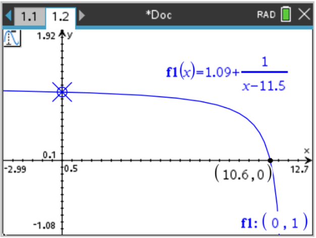
In order to take advantage of the HP motors, ideally, the robot should go as fast as possible, however, after a lot of testing, we found that the robot was not able to fully control the ball at high speeds, as it would usually push the ball out of bounds instead of getting it with the dribbler. Therefore, the speed was regulated depending on the distance to the ball (measured with the IR ring) using the following function:

\(v(r) = 1.087 + 1/(r-11.5)\), where \(r\) is the distance to the ball \(\in [0.00,10.0]\)
This equation was experimentally established with the goal of keeping speed at maximum until the robot gets very close to the ball, when the speed is quickly reduced.
Defending robot
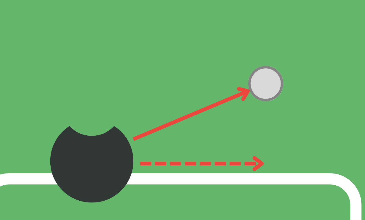
The idea for this robot was to keep it on the line line of the goal, always looking to keep the ball in front of it to block any goal attempts.Therefore, speed was regulated according to the angle and x-component to the ball. This meant that if the ball was in front of it, then it didn't have to move. However if the ball was far to the right or left, then speed had to be increased proportionally to the x-component of the ball, as shown in the following image:
